Noninvasive Dryer Done Notifications
Problem
My dryer is downstairs in my garage, and I cannot hear it when the cycle completes. I want to move my dryer clothes out when they are done to avoid wrinkling and needlessly delaying any loads waiting in the washer.
tl;dr solution
Background
I don’t own the place I live in. I can’t change much in the appliances that came with the house. I want something noninvasive that minimizes the chance of bricking the appliance or burning down the house.
Key Requirements
- Reliable detection of when the dryer is done.
- Notification on a remote device when the dryer is done.
- No modifications to the dryer’s internals.
Detecting When The Dryer Is Done
The dryer needs to spin a big motor and power a heating element hot enough to dry clothes. I assume that when the dryer is running, it is drawing a large amount of current, and when it is not running, it is drawing low or no current. We now need a way to detect high/low current draw without modifying internal circuitry.
Detecting Current Draw
I found a couple of options available that at least fulfill requirements 1 and 3:
CT (Current Transformer) Clamp

When current is running through the conductor, the current transformer provides a proportional current in the secondary winding. A current transformer is a split ring made of ferrite or soft iron. The conductor (wire) it is clamped around forms the primary winding, and the wire coiled round the ferrite ring forms the secondary winding.
In other words, by clamping the power cable we can measure the current being drawn by the appliance and combine it with something that can report the reading remotely.
Kill-A-Watt
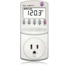
Kill-A-Watt is an electricity usage monitoring device manufactured by Prodigit Electronics that measures energy used by devices plugged directly into the meter. It displays a number of metrics on its LCD screen, including current.
However, it does not report readings remotely.
Reporting Current Draw Remotely
The system will be located at home. Since the laundry room likely does not have a ethernet drop, we will want to connect wirelessly. Bluetooth, Zigbee, and other protocols require a hub that speaks those protocols, which may not be ubiquitous. Almost everyone has WiFi at home.
Consuming Current Draw Data

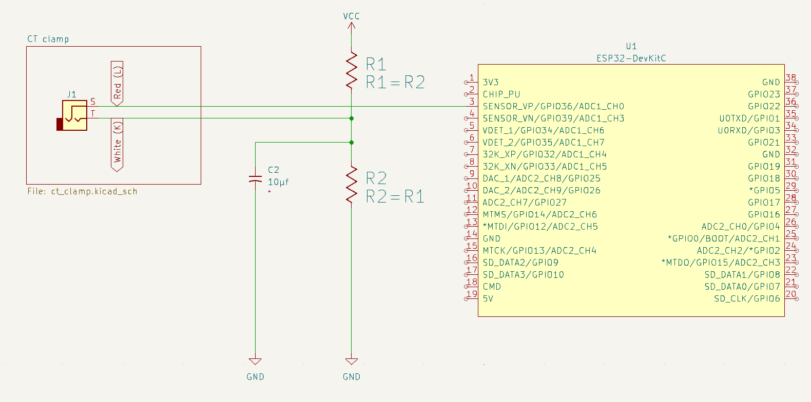
Pictured is the schematic for an SCT013 Current Transformer clamp manufactured by YHDC. Depending on the model, the CT clamp may include an internal burden resistor $R_3$. If there is no internal burden resistor, one must be added to your circuit across the $K$ and $L$ wires. The purpose of the internal burden resistor is to protect the circuit and allow measuring of voltage across the circuit, proportional to the current in the secondary winding of the transformer.
Many wireless microcontrollers have a analog to digital converter (ADC) pin
that lets you measure voltage. By feeding the ADC pin the voltage over the
burden resistor, we can calculate the current in the primary winding.
Calculating Current From Voltage
$$ I_s = I_p / N $$
Where $I_s$ is the current in Amps of the secondary winding, $I_p$ is the current in Amps of the primary winding (the power cable), and $N$ is the number of turns in the current transformer.
Measure the voltage across the burden resistor and apply Ohm’s law to get the current:
$$ I_p = \frac{R_3}{NV} $$
However, SCT013 documentation does not include the number of turns, nor does it include the internal burden resistor value. To work around this, we can measure $V$ with the clamp on a wire plugged into a Kill-A-Watt, which provides $I_p$ value.
Using Ohm’s law, we get this formula to calculate the constant ratio $T$ between $I_p$ and $V$:
$$ \frac{R_3}{N} = \frac{V}{I_p} = T $$
$T$ can then be used to obtain the current draw in the primary winding:
$$ I_p = \frac{T}{V} $$
Solution